Limitations
The Challenger 3500 limits grouped by subject, from weights and speeds to engines, fuel and autoflight. Learn the numbers here before the type rating.
Weight and CG
Weights
| Maximum ramp weight (MRW) | 40,750 lb (18,484 kg) |
|---|---|
| Maximum takeoff weight (MTOW) | 40,600 lb (18,416 kg) |
| Maximum landing weight (MLW) | 34,150 lb (15,490 kg) |
| Maximum zero fuel weight (MZFW) | 28,200 lb (12,791 kg) |
| Minimum flight weight (MFW) | 24,800 lb (11,249 kg) |
- Anything you load above the MZFW has to be fuel.
- Runway, climb or brake energy performance can bring the MTOW or the MLW below the structural figure.
- The CG must stay inside the approved envelope in every phase of flight. Load the airplane with the weight and balance manual. Retracting the gear barely moves the CG.
Where you can fly
Operating envelope
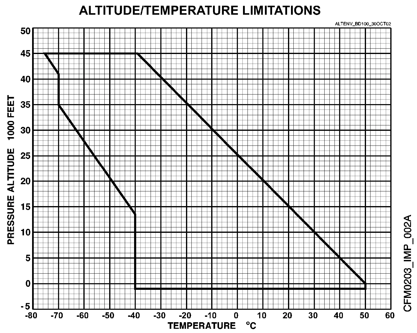
| Maximum operating altitude | 45,000 ft |
|---|---|
| Maximum takeoff and landing pressure altitude | 10,000 ft |
| Coldest ambient temperature for takeoff and landing | −40 °C |
| Hottest ambient temperature at sea level | +50 °C |
| Maximum tailwind for takeoff and landing | 10 kt |
| Maximum runway slope, uphill | +2% |
| Maximum runway slope, downhill | −2% |
| Load factor, flaps up | +2.6 g to −1.0 g |
| Load factor, flaps extended | +2.0 g to 0.0 g |
| Steepest glidepath, airports up to 5,000 ft | 4.5° |
- Approved for day and night, VMC and IMC, and flight into icing conditions.
- Minimum crew is two: a pilot and a copilot.
- Paved runways only. No aerobatics, no spins.
- Above 5,000 ft airport elevation the steepest allowed glidepath gets shallower. Steeper approaches, 4.5° to 5.5°, need the steep approach supplement.
- Demonstrated crosswind is 28 kt for takeoff and 24 kt for landing. It is not a limit.
- Work out performance from the CAFM or from the QRH Volume 1 tables, never a mix of the two.
Speed limits
Airspeeds
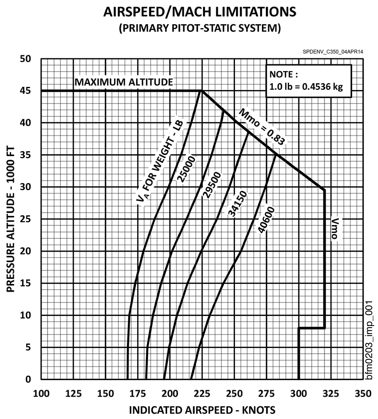
| VMO up to 8,000 ft | 300 KIAS |
|---|---|
| VMO from 8,001 to 29,475 ft | 320 KIAS |
| MMO above 29,475 ft | M 0.83 |
| Rough air speed (VRA) | 265 KIAS |
| Rough air Mach | M 0.75 |
| Gear retraction (VLO RET) | 200 KIAS |
| Gear extension (VLO EXT) | 250 KIAS |
| Gear extended (VLE) | 250 KIAS |
| VFE flaps 10° | 210 KIAS |
| VFE flaps 20° | 210 KIAS |
| VFE flaps 30° | 175 KIAS |
| Tire speed | 182 kt ground speed |
- Never exceed VMO or MMO on purpose, in climb, cruise or descent.
- Overspeed warnings use baro-corrected altitude, on the PFDs and on the standby instrument.
- VA changes with weight and altitude: read it from the chart. Full aileron or rudder, and manoeuvres close to the stall, only below VA.
- Large, rapid control reversals can break the structure at any speed, below VA too.
- Slowing down on purpose below the stick shaker onset is prohibited.
Ice and cold weather
Icing
| Icing conditions in flight | TAT 10 °C or below with visible moisture |
|---|---|
| No icing conditions, whatever the moisture | SAT −40 °C or below |
| Engine anti-ice on the ground | OAT 10 °C or below with visible moisture or a contaminated surface |
| Wing anti-ice for takeoff | OAT 5 °C or below with visible moisture or a contaminated surface |
| Wing anti-ice ON in icing conditions | at airspeeds below 210 KIAS |
| Fog that counts as visible moisture | visibility 1 mile (1,500 m) or less |
- With ICE DETECTED on, engine and wing anti-ice must be ON. In icing conditions engine anti-ice is always ON.
- Do not hold in icing conditions with the flaps out.
- Ice on the side windows can mean super-cooled large droplets: wing and engine anti-ice ON and get out of the icing.
- No takeoff with frost, ice, snow or slush on the wings, tail, control surfaces or engine inlets. Frost from cold-soaked fuel under the wing, or on top of the fuselage, is allowed under the cold weather supplement.
- After Type II, III or IV fluid, select wing anti-ice ON, if needed, only just before you set takeoff thrust.
HTF7350 engines
Powerplant
| N1, normal takeoff | 96.2% |
|---|---|
| N1, APR | 96.2% |
| N1, maximum continuous (CLB) | 95.9% |
| N1, maximum reverse | 70.7% |
| N2, normal takeoff | 98.0% |
| N2, maximum continuous (CLB) | 98.0% |
| N2, APR | 98.6% |
| N2 at idle, minimum | 46.0% |
| Normal takeoff thrust | 5 min |
| APR thrust, one engine inoperative | 10 min |
| Takeoff, APR and maximum reverse | 955 °C |
|---|---|
| Maximum continuous (CLB) | 950 °C |
| Ground start | 650 °C |
| Air start | 800 °C |
| Maximum oil temperature | 138 °C |
|---|---|
| Minimum oil temperature for takeoff | 27 °C |
| Minimum oil temperature above ground idle | 5 °C |
| Minimum oil temperature for a ground start | −40 °C |
| Minimum oil pressure at idle | 28 psi |
| Consecutive start cycles | 3, then 15 min cooling |
|---|---|
| Motoring after an aborted start | 30 s |
| Continuous cranking | 5 min, then 15 min cooling |
| Engine ground start, highest pressure altitude | 15,000 ft |
| Fuel icing inhibitor for takeoff | fuel below −20 °C, unless cold weather procedures are used |
| Reverse above idle, prohibited below | 40 KIAS |
| Reverse thrust ramps down from | 85 KIAS |
- Between 5 and 14 °C oil temperature you may go from idle up to, but not including, CLB thrust.
- In temperatures below −30 °C the minimum oil temperature for takeoff drops to 15 °C, with fuel icing inhibitor and the cold weather procedures.
- The air start ITT limit varies with N2. With N2 below 18% and ITT below 250 °C at start initiation, it is 400 °C.
- Minimum oil pressure rises with engine speed. Oil approved: Honeywell EMS 53110 Type II.
- Reversers on paved runways only: never in flight, never to back up, never on a touch-and-go.
Honeywell 36-150BD
APU
| APU operation | up to 37,000 ft |
|---|---|
| APU start in flight | up to 30,000 ft |
| APU start on the ground | up to 14,000 ft |
| Highest speed for an APU start | 285 KIAS |
| APU GEN | up to 30,000 ft |
| APU bleed for an engine start | up to 20,000 ft |
| APU bleed for air conditioning | up to 20,000 ft |
| Left engine start on APU air, on the ground | not above 9,000 ft |
| Hung start: abort if RPM after 30 s is below | 30% |
| Maximum RPM | 108% |
| Maximum EGT, start | 973 °C |
| Maximum EGT, running | 718 °C |
- On the ground: 3 start attempts with 1 min cooling after each, then 20 min cooling. Two more attempts, then wait at least 40 min.
- Six starts at 10 min intervals are allowed, then 1 h before the next attempt.
- In flight, after a failed or hung start, no further attempt until after landing.
- The APU must not run while the airplane is being de-iced or anti-iced with fluid.
Quantities and temperatures
Fuel
| Usable fuel, pressure refuel | 14,150 lb (6,420 kg) |
|---|---|
| Each wing, pressure refuel | 7,075 lb (3,210 kg) |
| Usable fuel, gravity refuel | 13,000 lb (5,900 kg) |
| Each wing, gravity refuel | 6,500 lb (2,950 kg) |
| Minimum fuel for a go-around, per side | 500 lb (227 kg) |
| Pressure refuelling | 55 psig maximum |
| Defuelling | −8 psig maximum |
| Total fuel above 13,700 lb | 250 lb |
|---|---|
| Total fuel 10,000 to 13,700 lb | 315 lb |
| Total fuel 4,700 to 10,000 lb | 450 lb |
| Total fuel below 4,700 lb | 600 lb |
| Highest bulk fuel temperature for takeoff | 50 °C |
|---|---|
| Minimum fuel for takeoff, wing bulk fuel at 45 °C or more | 2,800 lb |
| Lowest bulk fuel temperature for takeoff, Jet A | −30 °C |
| Lowest, Jet A-1, JP-5 and JP-8 | −35 °C |
| Lowest, Jet B and JP-4 | −40 °C |
| Maximum altitude on Jet B or JP-4 | 16,000 ft |
| Maximum altitude on TS-1 or RT, bulk fuel above 30 °C | 37,000 ft |
- Power and gravity transfer shut-off valves selected off for takeoff.
- With wing bulk fuel at 45 °C or more and under 1,000 lb a side, run the engine for 30 min at most.
- With FUEL IMBALANCE on, do not taxi or land until it is corrected, unless a bigger emergency exists.
- Mixing approved fuel types is allowed. The APU burns the same fuels as the engines.
Pressurization, electrics, controls, gear
Systems
| Maximum differential pressure (S/N 20887 and on) | 10.1 psi |
|---|---|
| Maximum negative differential pressure | −0.5 psi |
| Maximum differential pressure while taxiing | 0.1 psi |
| Maximum differential pressure for landing | 1.0 psi |
| Oxygen masks, highest cabin altitude | 40,000 ft |
| Passenger masks, prolonged use not recommended above | 25,000 ft cabin altitude |
| Pack must run when electrical power is on for over 30 min and OAT is above | 40 °C |
| Two or three generators, continuous | 400 A |
|---|---|
| One generator on the ground, continuous | 400 A |
| One generator in flight, continuous | 500 A |
| Transient, 5 min | 600 A |
| Lowest battery temperature for takeoff | −20 °C |
| Flap extension prohibited above | 18,000 ft |
|---|---|
| Gear extension prohibited above | 18,000 ft |
| Flight spoilers, lowest height | 500 ft AGL |
| Flight spoilers, lowest speed | approach speed + 8 KIAS |
- AIR SOURCE to TRIM AIR ONLY is not allowed on the ground.
- Flight spoilers to EMER only in an emergency or when a procedure calls for it.
- Respect the brake cooling time after a landing or a rejected takeoff before the next takeoff.
- Read the standby compass with the L and R WSHLD/WINDOW heat switched OFF for a moment.
- Hydraulic fluid: phosphate ester Type IV (Skydrol LD-4, Hyjet IV-A Plus).
Autopilot, autothrottle, navigation
Autoflight and avionics
| Autopilot engage in climb, cruise or descent | 700 ft AGL minimum |
|---|---|
| Autopilot on a precision approach, glidepath 3.5° or less | 80 ft AGL minimum |
| Autopilot on a precision approach, glidepath 3.5° to 4.5° | 160 ft AGL minimum |
| Autopilot on a visual or non-precision approach | 200 ft AGL minimum |
| Maximum altitude with yaw damper off | 31,000 ft |
| Autothrottle takeoff: engaged, N1 checked, HOLD active by | 80 KIAS |
| Autothrottle off, abnormal landing with flaps below 30° | by 200 ft AGL |
| Autothrottle off, radio altitude invalid | by 200 ft AGL |
| CDI scale, RNP APCH | 0.3 NM |
|---|---|
| CDI scale, RNP 1 | 1.0 NM |
| CDI scale, RNP 2 | 2.0 NM |
| CDI scale, RNP 4 and RNP 10 (pilot selected) | 4.0 NM |
| Longest leg, RNP 1 | 200 NM |
| Longest leg, RNP 2 | 400 NM |
| Longest leg, RNP 4 and RNP 10 | 500 NM |
| IAF speed, T-transition flown with VNAV | 210 KIAS maximum |
- Do not overpower the autopilot. Do not press XFR while typing on an FMS CDU.
- No autothrottle after an engine failure on takeoff or in a single-engine go-around until the flaps are up and you are at en route climb speed. Never on a touch-and-go.
- FMS approaches only with RNP APPR or LPV APPR on the PFD. LPV needs dual PFD, dual FMS and two GNSS/SBAS sensors to start (one to continue).
- No VNAV with QFE set, no VNAV after a go-around in the missed approach, no VFLC in a climb flown in Mach.
- Synthetic vision is for awareness only, never for navigation. TAWS alerts come first.
- Keep weather radar on at least one PFD or MFD for the whole flight. Data-linked weather is advisory.
Back to the systems
Each system module puts its own limits next to the panels and the procedures that use them.
My course