Electrical system
A 28 V DC system split into a left and a right channel. Two engine generators carry the load, the APU generator can share it or stand in for one or both, and two main batteries keep the essential loads going if every generator is lost.
Open the slidesPower sources
Where the power comes from
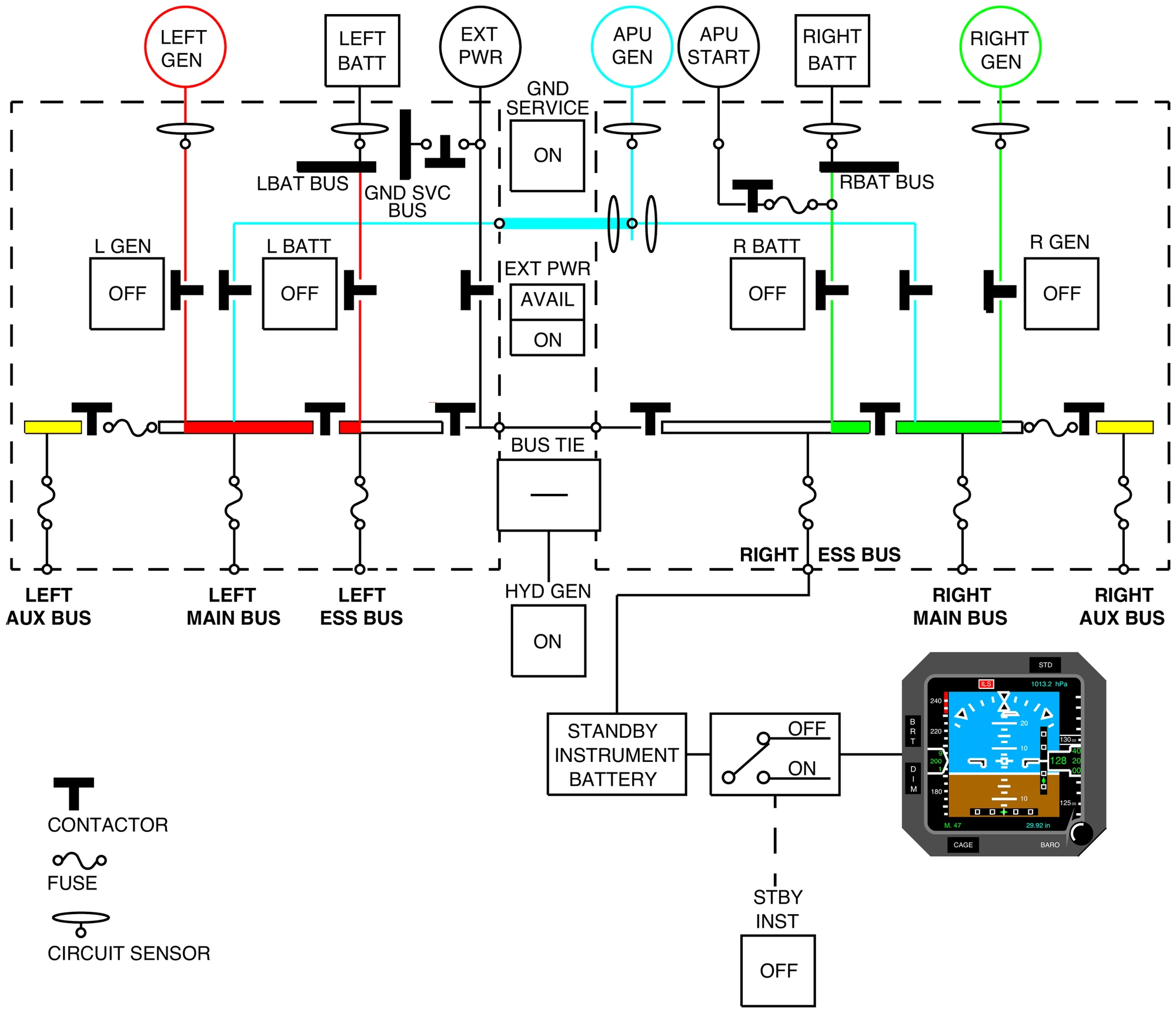
- Three identical, air-cooled generators: one on each engine and one on the APU. Either engine generator alone gives enough power for normal operations.
- The APU generator can share the load with the engine generators at low and medium altitudes, or replace one or both of them after a failure.
- Two main batteries supply every load on the ground, and the essential loads when the generators are inoperative.
- The standby instrument has its own 24 V DC battery in the nose landing gear bay, switched on with STBY INST.
- External DC power can be plugged in on the ground. A hydraulic motor driven generator is optional equipment.
- The left and right channels are kept apart, electrically and physically. External power and the APU generator can connect to both.
| System | 28 V DC |
|---|---|
| Generator rating | 12 kVA |
| Generator nominal output | 29.5 V |
| Main battery voltage | 24 V, nickel-cadmium |
| Main battery capacity | 44 Ah each |
Distribution
Buses, power centers and breakers
- Each side has an ESS, a MAIN, an AUX and a battery bus.
- The batteries connect to the essential buses, and keep the battery buses powered even with the battery switches OFF. An online generator feeds the main buses and charges its own side battery.
- With two or more generators online the bus tie is open. It closes automatically when external power is selected ON, and when a generator fails with the APU generator off line.
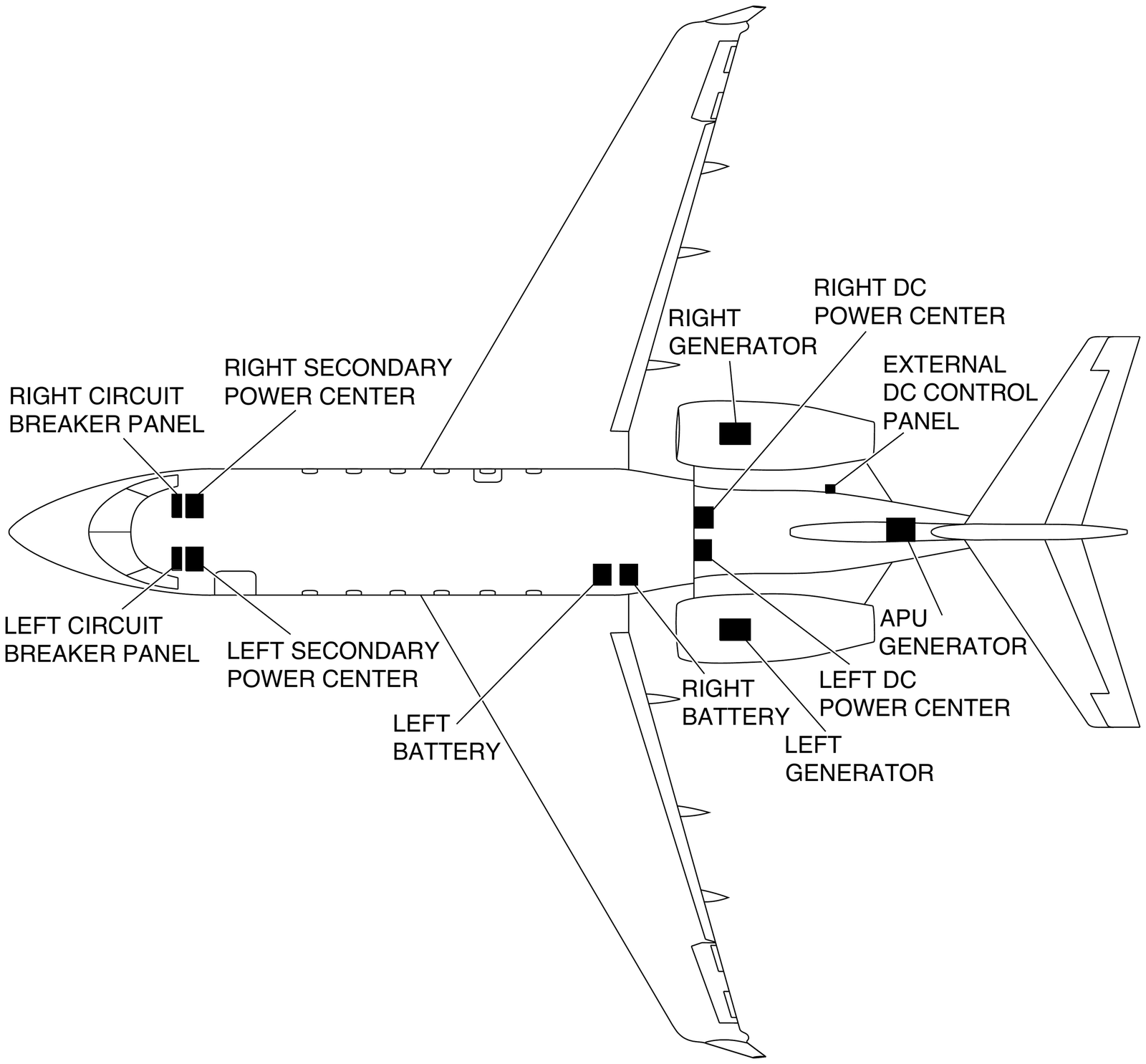
- Two DC power centers (DCPC) in the aft equipment bay switch the sources onto the buses. They couple both channels on the ground with only batteries or external power, and in flight with one generator. They also shed load automatically and isolate a bus or feeder that shorts.
- Two secondary power centers on the front equipment rack take power from the DCPCs and feed the forward loads.
- Six breaker panels: CB1 pilot and CB2 copilot in the cockpit, CB3 and CB4 in the left and right equipment racks, CB5 and CB6 on the left and right DC power centers.
| L AUX bus | Cabin AC power, pilot's foot warmers |
|---|---|
| R AUX bus | Cabin DC power, right window anti-ice, copilot's foot warmers |
| In flight, one engine generator and no APU generator | Both AUX buses unpowered |
Flight deck
ELECTRICAL panel and synoptic
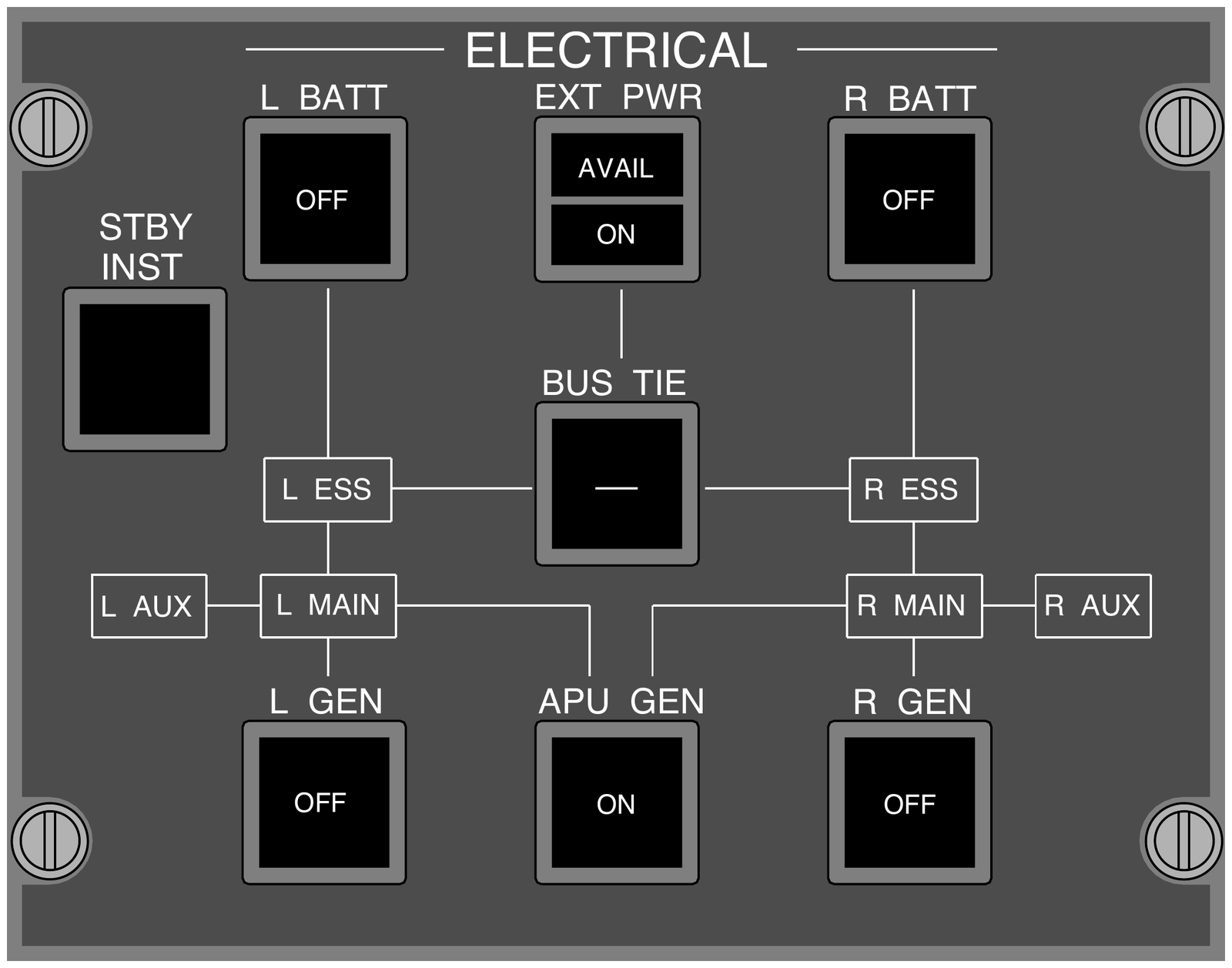
- The panel carries annunciators for the six buses: L and R ESS, MAIN and AUX.
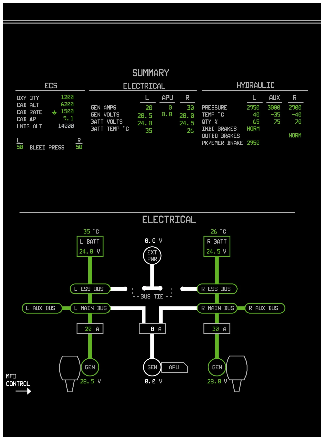
- Battery voltage and temperature show on the ELECTRICAL synoptic and the SUMMARY page. GPU voltage shows there too, but there is no reading of the amps drawn from the GPU.
- On the synoptic the EXT PWR symbol is white when available, green when ON and gone when disconnected. It appears once a GPU cable is plugged in and more than 5 V DC is sensed.
- Electrical warnings come with a triple chime, cautions with a single chime.
| L BATT, R BATT | Battery on or off. Selected off: OFF lights and the L (R) BATT OFF status message shows. |
|---|---|
| EXT PWR | Green AVAIL: GPU within limits. Push: ON lights and the GPU is connected. Push again to deselect it. |
| BUS TIE | Push: bus tie opened by hand, no automatic operation, BUS TIE MAN OPEN status message. Push again for automatic control. |
| L GEN, R GEN | Engine generator switches. Selected off: L (R) GEN OFF status message. |
| APU GEN | Controls the APU generator. Selected off: APU GEN OFF status message. |
| STBY INST | Switches on the standby instrument battery. |
Normal operation
External power, APU start and generators
- Ground power plugs in on the lower right side of the fuselage, just below the engine pylon.
- The main batteries do not have to be on to connect the GPU. With EXT PWR ON the bus tie closes and the whole DC system is powered.
- With EXT PWR ON no generator comes online, and any generator already online drops off. After engine start, select EXT PWR to AVAIL, disconnect the GPU and check the generators online.
- R BATT goes on before L BATT, so the APU cannot start uncommanded.
- APU start: START held for 3 seconds and released. The right battery is cut off from the R ESS bus and cranks the starter. The left battery keeps both essential buses powered.
- If the batteries are well discharged when a generator comes online, the charging current can give a short APU GEN OVERLOAD or L (R) GEN OVERLOAD caution.
| GPU accepted, approximately | 24 to 32 V |
|---|---|
| GPU regulated to | 28 V DC |
| GPU current limit | 1,500 A |
What not to exceed
Batteries and limits
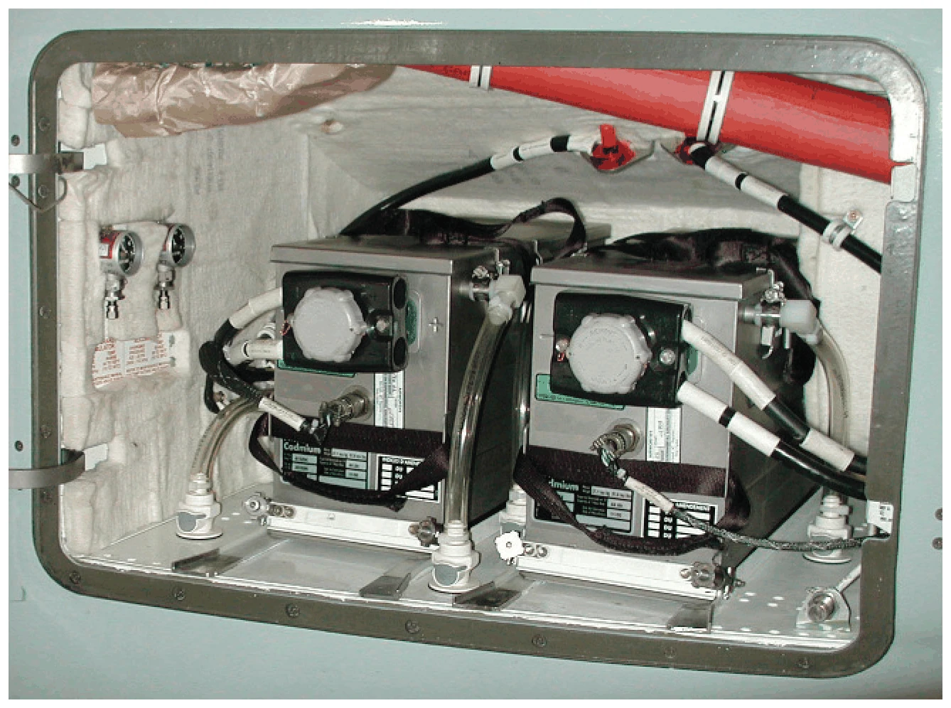
- The main batteries sit in the fuselage fairing aft of the left wing.
- With every generator lost, the batteries power the essential equipment for a limited time only.
| Generator load, two or three generators, continuous | 400 A |
|---|---|
| Generator load, one generator on the ground, continuous | 400 A |
| Generator load, one generator in flight, continuous | 500 A |
| Generator load, transient for 5 minutes | 600 A |
| Lowest battery temperature for takeoff | −20 °C |
| APU generator, maximum altitude | 30,000 ft |
| APU start, maximum altitude in flight | 30,000 ft |
| APU start, maximum altitude on the ground | 14,000 ft |
| L (R) BATT OVERHEAT, battery internal temperature above | 70 °C |
|---|---|
| L (R) GEN OVERLOAD, generator load above | 500 A |
| APU GEN OVERLOAD, APU generator load above | 500 A |
| STBY INST BATT FAULT, one cause: battery temperature above | 80 °C |
When it goes wrong
Warnings, cautions and the QRH
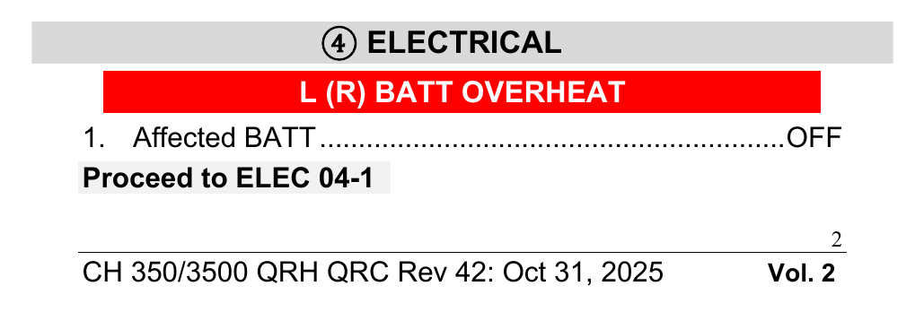
- L (R) BATT OVERHEAT (warning): battery internal temperature above 70 °C. Its Immediate Action Item is on the QRC, and the procedure goes on at ELEC 04-1.
- ESSENTIAL POWER ONLY (warning): main generation lost in the air. The essential buses run on the batteries only, and the MAIN and AUX buses are shed automatically in flight.
- L (R) GEN FAIL (caution): with the APU generator off line the bus tie closes automatically and, in flight, the AUX buses lose power.
- L (R) BATT FAIL (caution): the battery contactor failed, or the battery was taken off line automatically to protect it from overheat.
- L (R) ESS BUS FAIL and L (R) MAIN BUS FAIL: the bus is not powered. L (R) AUX BUS FAIL: not powered although a source is available. L (R) ESS BUS OFF and L (R) MAIN BUS OFF: the bus is serviceable but has no power. L (R) AUX BUS OFF: no source available, as in single generator operation.
- Indications that flicker, cycle or make no sense: use Unexpected Electrical Indications. Any reset may take the affected source off line and make things worse.
| Two main batteries, generators off | One hour |
|---|---|
| Integrated standby instrument, after loss of generated power | 3.5 hours |
| Endurance assumes L WSHLD / WINDOW on for no more than | 15 min |
| Endurance assumes APU start attempts, no more than | 3 |
| Each extra APU start attempt costs about | 2 min |
The full module
The slides take you through the sources and buses, the ELECTRICAL panel and synoptic, a normal power-up and the abnormals, then a 10-question test.
Open the slides