Aircraft general
A low-wing jet with swept wings, winglets and two Honeywell HTF7000 engines in pods. Engine-driven hydraulics work the brakes, gear, nosewheel steering, flaps, spoilers, reversers, elevator and rudder. The ailerons are manual.
Open the slidesThe airplane
Size, turning room and danger areas
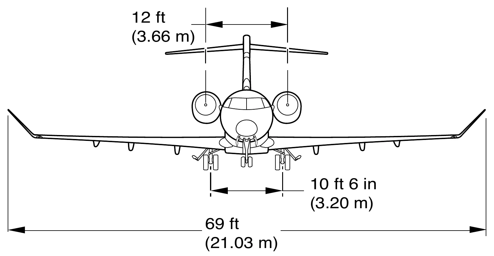
| Wing span | 69 ft (21.03 m) |
|---|---|
| Length | 68 ft 8 in (20.92 m) |
| Height, at empty weight | 20 ft (6.1 m) |
| Main gear track | 10 ft 6 in (3.20 m) |
| Nosewheel steering angle, maximum | 65° |
| Minimum pavement width, 180° turn | 53 ft (16.15 m) |
| Wingtip turn circle, diameter | 101 ft 1 in (30.82 m) |
| Nosewheel angle when towing | 120° maximum |
- The 53 ft pavement width includes a 5 ft safety margin. The turn figures assume full steering, idle thrust on both engines, no differential braking, a dry runway, maximum weight and an aft centre of gravity.
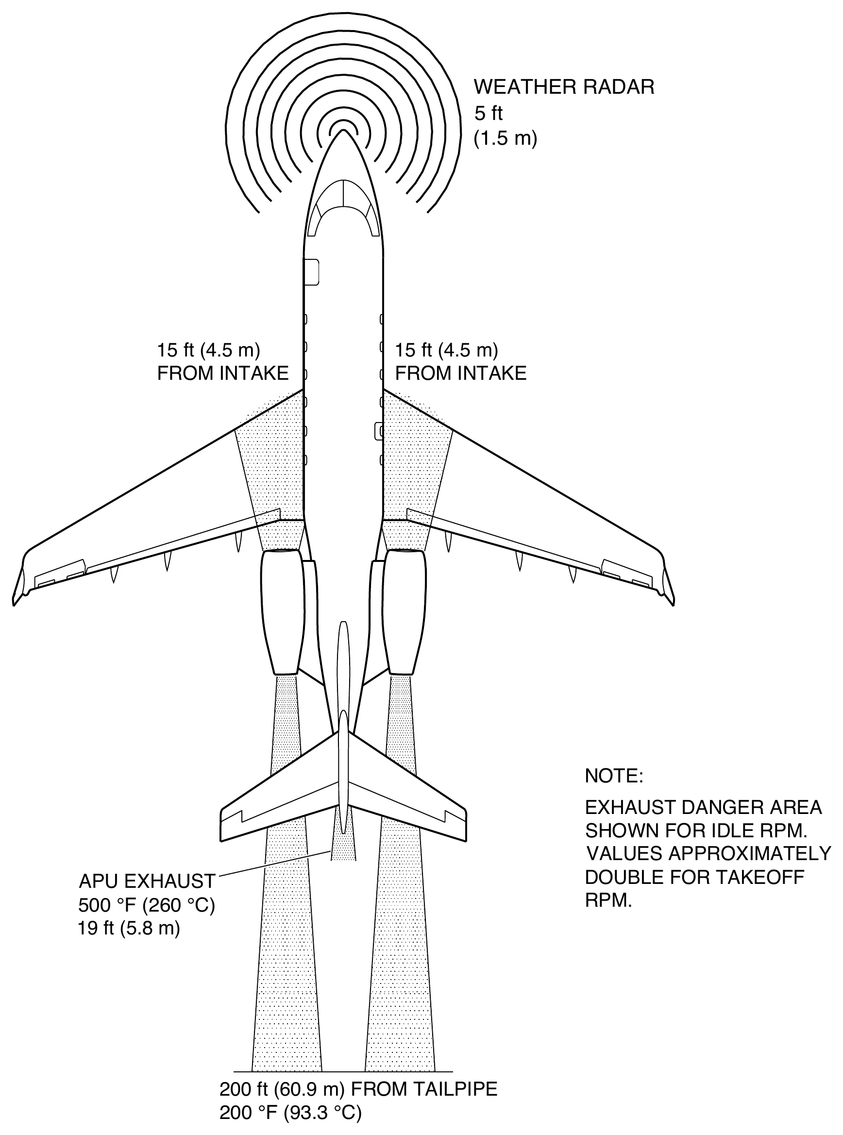
- Nobody stands within 5 ft in front of the weather radar while it transmits. A radar antenna that transmits without scanning is even more dangerous.
- Keep 15 ft clear of each engine intake. Behind the tailpipe the exhaust is dangerous for 200 ft at idle, where it is still 200 °F. At takeoff power the exhaust danger area roughly doubles.
- Towing needs the torque links connected and the steering de-energized. Past 120° the NWS LIMIT EXCEEDED caution shows. At about 123° indicator pins on the nose gear shear off, a sign that the steering feedback linkage may be damaged.
Cockpit and doors
Flight deck and the five monitored doors
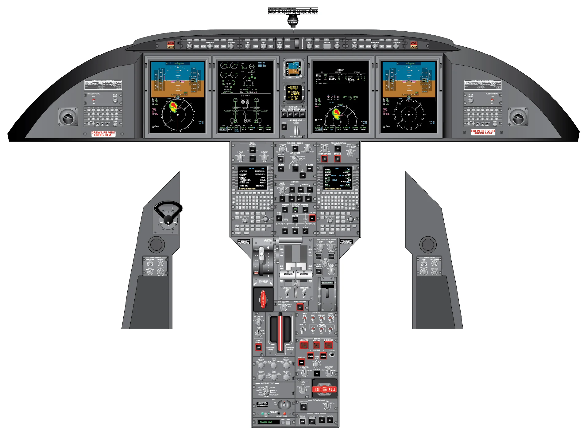
- Circuit breaker panels: CB 1 pilot and CB 2 copilot, CB 3 and CB 4 on the left and right equipment racks, CB 5 and CB 6 in the left and right DC power centres.
- Master disconnect switch on each control wheel: while held, the autopilot disconnects and pitch trim and the stall pusher are off. On release, trim and pusher come back at once; the autopilot stays off. On JAA approved aircraft the stall pusher stays active.
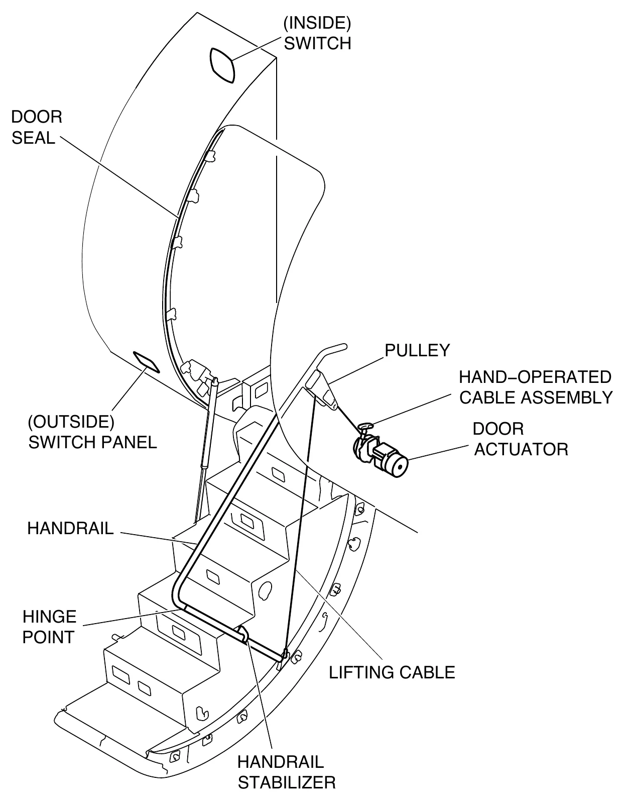
- The passenger door normally closes electrically. From inside, hold the switch for at least 7 seconds before the motor starts, then turn the lever down about 100° until the green flag shows. A red flag means unlocked. Air conditioning supply OFF before closing is recommended to avoid a pressure bump.
- The passenger door will not open while cabin pressure keeps its vent flap shut. Its circuit breaker, PAX DOOR, is on the LEFT BATT bus (CB3-C7).
| Passenger door | Left side, forward. Opens out and down with its own airstair. Locked, it is an airtight plug. |
|---|---|
| Emergency exit | Over the right wing. Type III plug hatch. Opens from inside or outside; goes back in only from inside. |
| Cargo bay door | Forward of the left engine nacelle, opens inward and up. Not an emergency exit. |
| Aft equipment bay door | Rear fuselage, on the centreline. Opens down. |
| Battery bay door | Left aft wing-to-fuselage fairing, over the main batteries. |
When a door is not closed
Door cautions and status messages
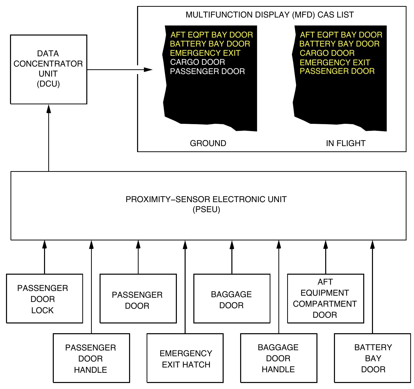
- A magnet and proximity sensor at each door feed the PSEU, then the DCU, then the CAS list on the MFD. Each door caution comes with a single chime.
- In flight, every door message is an amber caution.
- On the ground, EMERGENCY EXIT, AFT EQPT BAY DOOR and BATTERY BAY DOOR are amber cautions.
- On the ground, PASSENGER DOOR (S) and CARGO DOOR (S) are status messages while the left engine run switch is OFF. With the switch ON they become PASSENGER DOOR (C) and CARGO DOOR (C).
- PASSENGER DOOR (C) in flight means one or more door locking pins may not be fully engaged.
- PASSENGER DOOR (C) is inhibited for landing only. The other door messages are inhibited for takeoff and landing.
The full module
The slides cover the aircraft on the ground, the flight deck, how each door opens and closes, and the door cautions with their QRH pages. A 10‑question test closes the module.
Open the slides